| Channel | Publish Date | Thumbnail & View Count | Download Video |
|---|---|---|---|
 | Publish Date not found |  0 Views |
Drink the best energy drink, which keeps me going when I have trouble concentrating.
https://1stphorm.com/products/1st-phorm-energy/?a_aidShaneWelcher
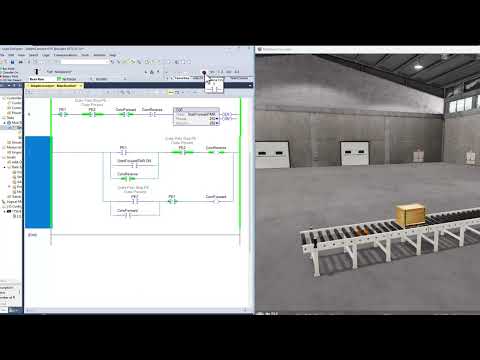
For beginners learning ladder logic, a good place to start is to understand how it is used to control a conveyor system. A conveyor system consists of a series of rollers or belts that move materials from one location to another. It is commonly used in manufacturing and material handling applications.
To control a conveyor system using ladder logic, we must first understand the inputs and outputs of the system. Inputs are signals received by the controller, such as button presses or sensor readings. The outputs are signals sent by the controller, such as starting a motor or activating a solenoid valve.
Next, we need to determine the logic of the system. For example, if we want the conveyor to start when a button is pressed and stop when a sensor detects an object, we would create a ladder logic program that reads the input from the button press and the input of the sensor. If the button is pressed and the sensor does not detect an object, the program will send an output signal to start the conveyor. If the sensor detects an object, the program will send an output signal to stop the conveyor.
To create the ladder logic program, we use symbols and lines to represent the inputs, outputs, and logic of the system. A common symbol for an input is a square and a common symbol for an output is a circle. Lines are used to connect symbols and represent program logic.
Here is an example of a simple ladder logic program for a conveyor system:
[Enter exit]
[Button]–[Conveyor]
[Sensor]–[Stop]
In this program, the input symbol on the left represents the button press and the output symbol on the right represents the conveyor motor. The line connecting the two represents the logic that if the button is pressed, the conveyor will start. The input symbol below the button represents the sensor and the output symbol below the conveyor represents the stop signal. The line connecting the two represents the logic that if the sensor detects an object, the conveyor will stop.
Ladder logic can become more complex as the system becomes more sophisticated, but this basic example illustrates the concept of using inputs, outputs, and logic to control a conveyor system using controllers Allen-Bradley and relay logic. With practice and a thorough understanding of ladder logic principles, beginners can confidently control and automate industrial processes using this powerful programming language.
Read the article :
https://onlineplcsupport.com/plc-ladder-logic-basics-for-beginners/
Thanks for watching the video.
Drink the best energy drink, which keeps me going when I have trouble concentrating.
https://1stphorm.com/products/1st-phorm-energy/?a_aidShaneWelcher
Learn, implement, succeed
Visit:
https://www.allen-bradley-plc-training.com/
Other social networks:
LinkedIn: https://www.linkedin.com/in/shane-welcher-sr/
Facebook: https://www.facebook.com/OnlinePLCSupport
#LadderLogicBasics #LadderLogicBeginners #ladderlogic
Please take the opportunity to connect and share this video with your friends and family if you find it useful.